英语
英语 德语
德语 阿拉伯语
阿拉伯语Content
- 1 What Is Steel Forging and How Does the Process Work
- 2 Main Steel Forging Methods and When to Use Each
- 3 Step-by-Step: How Steel Forging Is Done in Practice
- 4 Steel Grades Commonly Used in Forging and Their Properties
- 5 Key Design Rules for Forgeable Steel Parts
- 6 Steel Forging vs. Casting vs. Machining from Bar Stock
- 7 Common Defects in Steel Forging and How to Prevent Them
- 8 Industries That Rely on Steel Forging and Why
- 9 Quality Standards and Certifications for Steel Forgings
- 10 Frequently Asked Questions About Steel Forging
- 10.1 What is the minimum order quantity for closed-die steel forgings?
- 10.2 How long does it take to get steel forgings made?
- 10.3 Can stainless steel be forged using the same equipment as carbon steel?
- 10.4 Is warm forging different from hot forging?
- 10.5 How do I specify a forging correctly on a drawing?
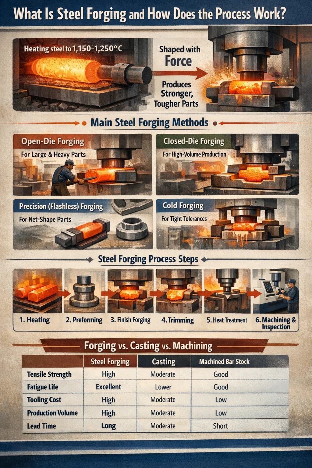
What Is Steel Forging and How Does the Process Work
Steel forging is a manufacturing process in which solid steel billets or bars are shaped under compressive force — using hammers, presses, or dies — to produce parts with superior mechanical properties compared to cast or machined alternatives. The result is a grain structure that follows the contours of the part, delivering tensile strengths typically 20–40% higher than equivalent cast steel components. If you need parts that handle fatigue, impact, or cyclic loading — connecting rods, crankshafts, flanges, gears — forging is usually the most reliable route to get there.
At its core, the process involves heating steel to a specific temperature range (usually between 1,100°C and 1,250°C for carbon and alloy steels), then applying force to plastically deform the material into the desired shape. The elevated temperature reduces flow stress and improves ductility, making the metal easier to shape without cracking. Once cooled, the forged part undergoes post-process heat treatment, machining, and inspection before shipping.
Steel forging is not a single technique. It branches into several distinct methods, each suited to different geometries, volumes, and tolerance requirements. Understanding how each method works — and where it falls short — is the starting point for any engineer or buyer trying to make the right call on a forging project.
Main Steel Forging Methods and When to Use Each
Each steel forging method produces parts with different dimensional tolerances, surface conditions, and tooling costs. Choosing incorrectly adds cost, extends lead times, or results in parts that need excessive secondary machining.
Open-Die Forging
Open-die forging (also called free forging or smith forging) uses flat or simple-shaped dies that do not fully enclose the workpiece. The steel is manipulated between the dies through a series of compressions, stretches, and rotations. This is the method used for large shafts, cylinders, rings, and ingots — parts that can weigh anywhere from a few kilograms to over 200 tonnes.
Open-die forging is the go-to choice when part size exceeds the capacity of closed dies, or when production quantities are too low to justify expensive tooling. Dimensional tolerances are wider (typically ±3–6 mm), so significant machining is expected afterward. Steel grades like 4140, 4340, and 316 stainless are routinely processed this way for oil and gas, power generation, and heavy equipment industries.
Closed-Die Forging (Impression-Die Forging)
Closed-die forging uses a matched set of dies with a cavity machined to the approximate shape of the finished part. The heated billet is placed between the dies, and force is applied until the steel fills the cavity completely, with excess material flowing out as flash around the parting line. The flash is later trimmed off.
This method produces tighter tolerances (typically ±0.5–1.5 mm depending on part complexity and size), better surface finish, and more consistent geometry than open-die work. Tooling costs are high — a full set of dies for a medium-complexity part can cost $15,000–$80,000 or more — so closed-die forging makes economic sense primarily for medium to high production volumes. Automotive connecting rods, wheel hubs, and valve bodies are classic applications.
Flashless (Precision) Forging
Flashless forging eliminates the flash by precisely controlling billet volume and die geometry so material fills the cavity without overflow. The result is a net-shape or near-net-shape part that requires minimal post-forging machining. Tolerances as tight as ±0.1–0.3 mm are achievable.
This process demands precise billet preparation and higher tooling investment, but material savings of 10–20% compared to conventional closed-die forging make it attractive for high-volume production of complex parts like gears, bevel gears, and suspension components.
Roll Forging
Roll forging passes a heated steel bar between two rolls with shaped grooves, reducing its cross-section and elongating it simultaneously. It is typically used as a preforming step before closed-die forging, but it is also used as a final process for tapered shafts, leaf springs, and rail components. The continuous nature of the process makes it highly efficient for elongated parts.
Upset Forging
Upset forging increases the cross-sectional area of a steel bar or rod by compressing it along its axis, shortening the length and increasing the diameter in a specific zone. Bolts, studs, valves, and flanged shafts are produced this way. High-speed upset forging machines can produce thousands of parts per hour, making this one of the most productive forging methods for fasteners and similar hardware.
Cold Forging
Unlike the methods above, cold forging is performed at or near room temperature. The steel work-hardens during the process, which actually increases surface hardness and strength. Tolerances are exceptionally tight (±0.05–0.1 mm), and surface finish is excellent, often eliminating the need for any turning or grinding. The trade-off is higher press forces required and limitations on part geometry and steel grade. Low-carbon and medium-carbon steels are most suitable for cold forging.
Step-by-Step: How Steel Forging Is Done in Practice
Knowing the process steps matters whether you are designing a part for forgeability or auditing a supplier's production floor. Here is how a standard closed-die steel forging sequence runs from raw material to finished part.
- Material Selection and Billet Preparation: The appropriate steel grade is selected based on the mechanical property requirements of the finished part. Common grades include 1045 (medium-carbon, general industrial), 4140 (chromium-molybdenum, high-strength), 4340 (nickel-chromium-molybdenum, aerospace), and 17-4 PH stainless (corrosion-resistant, high-strength). The bar stock or billet is cut to the calculated volume — slightly oversized to account for flash and scale loss.
- Heating: Billets are loaded into a gas-fired or induction furnace and brought to the target forging temperature. For most carbon and alloy steels, this is 1,150–1,250°C. Temperature uniformity across the billet cross-section is critical — a temperature gradient of more than 50°C can result in cracking or incomplete die fill. Induction heating is preferred for tight temperature control and reduced scale formation.
- Descaling: Hot steel develops an oxide scale layer during heating. Before forging, this scale is removed by high-pressure water jets (typically 100–200 bar) or by a first light blow in the die, which breaks the scale and prevents it from being pressed into the part surface, causing surface defects.
- Preforming (if required): Complex parts often require one or more preforming steps to redistribute metal mass closer to the final shape before the finish die impression. This reduces die wear and improves metal flow in the final blow. Preforming is done in separate die cavities on the same press or hammer.
- Finish Forging: The preformed billet is transferred to the finish die cavity and struck — either by a hammer (gravity or steam hammer delivering repeated blows) or a press (mechanical or hydraulic press delivering a controlled single stroke). The steel fills the cavity completely, and flash extrudes around the parting line.
- Flash Trimming: While still hot (or after cooling, for trimming presses), the forging is placed in a trimming die and the flash is punched off in a single stroke. For precision parts, the trimmed forging may be re-struck in a sizing die while still warm to correct any spring-back and improve dimensional accuracy.
- Heat Treatment: Depending on the steel grade and final mechanical property requirements, forged parts undergo normalizing, annealing, quenching and tempering, or solution treating and aging. Quenching and tempering of 4140 steel, for example, can bring tensile strength from 655 MPa (normalized) to over 1,000 MPa.
- Machining: Even near-net-shape forgings typically require CNC turning, milling, drilling, and grinding to achieve final dimensional tolerances, surface finish, and features (threads, bores, keyways) that cannot be forged directly.
- Inspection and Testing: Finished forgings are inspected dimensionally (CMM or manual gauging), visually (surface cracks, laps, seams), and often by non-destructive testing — magnetic particle inspection (MPI) for surface defects, ultrasonic testing (UT) for internal voids. Mechanical testing on sample coupons verifies hardness, tensile strength, impact toughness, and fatigue performance.
Steel Grades Commonly Used in Forging and Their Properties
Material selection is inseparable from the forging process. The steel grade determines forging temperature range, die life, required press capacity, post-forging heat treatment, and ultimately the performance of the finished part.
| Steel Grade | Forging Temp Range | Tensile Strength (Q&T) | Key Applications |
|---|---|---|---|
| AISI 1045 | 1,150–1,230°C | ~570–700 MPa | Shafts, gears, couplings |
| AISI 4140 | 1,100–1,230°C | ~900–1,100 MPa | Flanges, drill collars, axles |
| AISI 4340 | 1,100–1,200°C | ~1,000–1,500 MPa | Landing gear, crankshafts, aerospace |
| AISI 316 Stainless | 1,149–1,260°C | ~515–690 MPa | Valves, fittings, marine hardware |
| F51 Duplex SS | 1,050–1,150°C | ~620–880 MPa | Subsea components, chemical plant |
| 17-4 PH Stainless | 1,040–1,150°C | ~930–1,310 MPa | Aerospace, medical, pump shafts |
One practical note on stainless steel forging: austenitic grades like 316 have higher flow stress than carbon steels, meaning the press needs more capacity for the same part size. They are also more prone to strain hardening, which can cause cracking if reheating between passes is not done correctly. Duplex grades are even more sensitive to temperature — working outside the narrow forging window can destabilize the ferrite-austenite balance and degrade corrosion resistance.
Key Design Rules for Forgeable Steel Parts
Parts designed without forging in mind often end up costing significantly more to produce, or they fail to take advantage of the process's structural benefits. Applying these design principles from the start avoids expensive redesigns later.
Draft Angles
All vertical surfaces in a closed-die forging need a draft angle so the part can be ejected from the die. Standard draft for steel forgings is 5–7° on external surfaces and 7–10° on internal surfaces. Zero-draft or negative-draft features require more complex tooling with ejector pins or split dies, which increases cost significantly.
Fillet and Corner Radii
Sharp internal corners create stress concentrations in the die as well as in the finished part. A minimum internal fillet radius of 3 mm is a practical starting point, with 6 mm or larger preferred in heavily loaded zones. External corner radii should be at least 1.5 mm. Parts with proper fillets show fatigue life improvements of up to 3× compared to those with sharp transitions.
Parting Line Placement
The parting line is where the two die halves meet. It should be placed at the largest cross-section of the part to minimize die depth and flash. A straight, flat parting line is the simplest and cheapest option. Curved or angled parting lines add tooling complexity but may be necessary for certain geometries.
Section Thickness Variation
Large variations in cross-section thickness within the same part create uneven metal flow during forging. Thin sections fill faster and cool faster than thick ones, leading to underfill or cracking. As a rule of thumb, the ratio of maximum to minimum wall thickness in a steel forging should not exceed 4:1 without careful preform design to pre-distribute material.
Grain Flow Orientation
One of the most significant advantages of steel forging over casting or bar stock machining is the ability to align the grain flow with the highest stress direction in service. A connecting rod forged with longitudinal grain flow along the rod axis has far better fatigue resistance than one machined from bar stock, where the grain runs transversely across critical sections. Design the part so the primary load axis aligns with the main forging direction.
Steel Forging vs. Casting vs. Machining from Bar Stock
Engineers frequently face the choice between forging, casting, and machining when selecting a manufacturing route for structural steel parts. Each method has a distinct performance and cost profile.
| Criterion | Steel Forging | Casting | Machined Bar Stock |
|---|---|---|---|
| Tensile Strength | High (grain-refined) | Moderate (porosity risk) | Good (depends on grade) |
| Fatigue Life | Excellent | Lower (internal defects) | Good if grain aligned |
| Geometric Complexity | Moderate | High | High (CNC) |
| Tooling Cost | High (dies) | Moderate (patterns/molds) | Low to none |
| Unit Cost at High Volume | Low | Low to moderate | High (material waste) |
| Internal Defects | Minimal (voids closed) | Possible (shrinkage, porosity) | Depends on bar quality |
| Lead Time (prototype) | Long (die manufacturing) | Moderate | Short |
The decision typically comes down to three factors: annual production volume, required mechanical performance, and part complexity. For parts with complex internal passages or undercuts, casting often wins on geometry alone. For high-volume structural parts in automotive, aerospace, or oil and gas, forging nearly always wins on performance and lifecycle cost. Machining from bar stock makes the most sense for prototypes, very small batches, or parts that are simply too small to forge economically.
Common Defects in Steel Forging and How to Prevent Them
Even with correct process parameters, steel forgings can develop defects that compromise structural integrity. Knowing what causes each defect and how to catch it early prevents costly field failures.
Laps and Folds
Laps form when a surface wrinkle or overhang is folded back and forged into the part surface without bonding. They appear as linear surface defects, typically running parallel to the parting line. The root cause is usually incorrect preform shape, excessive flash, or poor metal flow distribution in the die. Magnetic particle inspection reliably detects laps on the surface. Prevention requires proper preform design and die cavity optimization.
Underfill
Underfill means the die cavity was not completely filled with steel during forging, leaving shallow depressions on the part surface. Causes include insufficient billet weight, too low a forging temperature, excessive flash that bleeds material away before the cavity fills, or inadequate press capacity. Dimensional inspection will catch underfill in most cases, but it is better caught in the first production run with sample sectioning.
Cracking
Surface cracks develop when the steel is forged at too low a temperature (below the ductile-to-brittle transition range), when the strain rate is too high, or when the steel has excessive sulfur or phosphorus content promoting hot shortness. Internal cracks (burst defects) occur when tensile stresses develop in the core during forging, often in heavy sections. Maintaining forging temperature above 1,050°C for most alloy steels and avoiding excessive reduction per pass prevents the majority of cracking defects.
Decarburization
Extended exposure to air at high temperatures causes carbon to diffuse out of the steel surface layer, creating a soft, low-carbon zone that reduces hardness and fatigue resistance. Decarburization depth of 0.3–0.8 mm is not uncommon in parts heated in open-flame furnaces. Using controlled-atmosphere furnaces or induction heating significantly reduces decarburization, and machining off the affected layer is the standard remediation when it does occur.
Die Shift
Die shift happens when the upper and lower die halves are misaligned during forging, producing a part that is offset at the parting line. Even a 0.5 mm shift can cause a part to fail dimensional inspection. Regular die alignment checks and proper locating key maintenance prevent this defect in production.
Industries That Rely on Steel Forging and Why
The demand for steel forging is driven by industries where structural failure is not an option. Understanding where and why forging is specified helps buyers justify tooling investment and helps engineers make the case for forging over competing processes.
- Automotive: Connecting rods, crankshafts, steering knuckles, wheel hubs, camshafts, and transmission gears are nearly universally forged. A typical passenger car contains 35–45 kg of forged steel parts. The fatigue and impact resistance of forged steel is the reason these safety-critical components are not cast.
- Oil and Gas: Drill bits, drill collars, BOP components, valve bodies, flanges (ANSI/ASME B16.5), and subsea connectors require forging to withstand extreme downhole pressures (up to 15,000 psi working pressure in some applications) and corrosive environments. ASME/ANSI and API standards mandate forging for many of these components.
- Aerospace: Landing gear struts, wing attach fittings, engine mounts, and turbine discs are forged from high-strength alloy steels and superalloys. The aerospace industry's strict requirements for traceability, certified material test reports, and non-destructive testing make forging the default choice for structural airframe components.
- Power Generation: Steam turbine rotors, generator shafts, and pressure vessel heads in nuclear and conventional power plants are among the largest forgings produced — single open-die forgings can weigh 150–300 tonnes. The material integrity required for components operating under combined thermal and mechanical stress for 30–60 years is only achievable through controlled forging and heat treatment.
- Mining and Construction Equipment: Bulldozer track links, excavator bucket pins, rock crusher hammers, and drill rods are subjected to severe impact and abrasive wear. High-manganese and low-alloy steel forgings resist deformation and fracture under these conditions far better than cast alternatives.
- Defense: Artillery projectiles, armor-piercing penetrators, tank track components, and gun barrels are forged to meet military specifications requiring specific hardness, toughness, and dimensional consistency that cannot be achieved by other processes.
Quality Standards and Certifications for Steel Forgings
Purchasing steel forgings without referencing applicable standards leaves buyers exposed to quality variability and non-conforming parts. The major standards governing steel forging quality are worth knowing before writing a purchase order.
- ASTM A668 / A668M: Standard specification for carbon and alloy steel forgings for general industrial use. Covers eight classes with mechanical property requirements from tensile strength of 485 MPa (Class D) up to 830 MPa (Class L).
- ASTM A182: Covers forged or rolled alloy and stainless steel pipe flanges, forged fittings, and valves for high-temperature service. Widely referenced in oil and gas and chemical processing specifications.
- ASTM A105: Standard for carbon steel forgings for piping applications at ambient and higher temperatures. This is one of the most commonly called-out specifications for flanges and fittings in industrial piping systems.
- API 6A / 6D: American Petroleum Institute standards for wellhead and Christmas tree equipment (6A) and pipeline valves (6D). These standards define material classes, test requirements, and traceability documentation for forged components used in hydrocarbon service.
- AMS (Aerospace Material Specifications): SAE AMS standards like AMS 2750 (pyrometry for heat treatment) and material-specific AMS grades (e.g., AMS 6414 for 4340 steel) govern aerospace forgings. Compliance requires documented furnace calibration, certified material test reports, and first article inspection.
- ISO 9001 / IATF 16949: Quality management system certifications for general industrial (ISO 9001) and automotive (IATF 16949) forging suppliers. These certifications indicate the supplier operates a documented quality system but do not by themselves guarantee product compliance to specific mechanical specifications.
Always request material test reports (MTRs), dimensional inspection reports, and NDE reports with each forging shipment. For critical applications, witness testing at the forge shop is standard practice in aerospace and nuclear procurement.
Frequently Asked Questions About Steel Forging
What is the minimum order quantity for closed-die steel forgings?
Most closed-die forging shops set a minimum order quantity (MOQ) of 100–500 pieces for new tooling projects, though this varies by part size and complexity. For small, simple parts, some shops will consider 50-piece trial runs. The high tooling cost is the main constraint — die cost divided across fewer parts raises per-unit cost significantly. Open-die forgings have no practical MOQ minimum since no custom tooling is required.
How long does it take to get steel forgings made?
For closed-die forgings with new tooling, lead times typically run 10–16 weeks: 4–6 weeks for die design and manufacturing, 1–2 weeks for first-article forging trials, and 2–4 weeks for heat treatment and machining of production parts. Open-die forgings for large parts can take 8–20 weeks depending on forge shop capacity and steel billet availability. Repeat orders from existing dies are usually 4–8 weeks.
Can stainless steel be forged using the same equipment as carbon steel?
Yes, the same hammers and presses are used, but stainless steel — particularly austenitic grades — requires higher forging forces than carbon steel at equivalent temperatures due to its higher flow stress. A press rated for a specific carbon steel part size may need to be de-rated or the part split into smaller operations when switching to stainless. Die life is also typically shorter when forging stainless steel due to higher interface pressures and abrasive oxide scale.
Is warm forging different from hot forging?
Yes. Warm forging is performed in the temperature range between cold forging and hot forging — typically 650–950°C for steel. At these temperatures, flow stress is lower than at room temperature (making forming easier), but the steel does not form the heavy oxide scale seen in hot forging. The result is better surface finish and tighter tolerances than hot forging, with lower press forces than cold forging. Warm forging is used for medium-complexity parts where surface quality is important but cold forging forces would be impractically high.
How do I specify a forging correctly on a drawing?
A complete forging specification on a drawing should include: the steel grade (ASTM, AISI, or AMS designation), the heat treatment condition and required hardness or tensile/yield strength, draft angle requirements, fillet and corner radii minimums, surface finish (Ra value) for as-forged surfaces, allowable flash extension at the parting line, required NDE methods (MPI, UT) and acceptance criteria, and the applicable material test report requirements. Referencing the applicable ASTM standard (e.g., ASTM A668, Class F) ties all material and testing requirements together cleanly.