英语
英语 德语
德语 阿拉伯语
阿拉伯语Content
- 1 How Steel Forging Works: The Direct Answer
- 2 The Raw Material: Choosing the Right Steel for Forging
- 3 Heating the Steel: Temperature, Furnaces, and Scale Control
- 4 Open-Die Forging: Flexibility for Large and Custom Parts
- 5 Closed-Die Forging: Precision and High-Volume Production
- 6 Roll Forging and Ring Rolling: Specialized Shaping Methods
- 7 Cold and Warm Forging: Working Steel Below Red Heat
- 8 Forging Equipment: Hammers, Mechanical Presses, and Hydraulic Presses
- 9 What Happens to the Grain Structure During Steel Forging
- 10 Heat Treatment After Forging: Completing the Metallurgical Cycle
- 11 Quality Control and Testing in Steel Forging
- 12 Common Defects in Steel Forgings and Their Causes
- 13 Where Forged Steel Parts Are Used: Industry Applications
- 14 Modern Developments in Steel Forging Technology
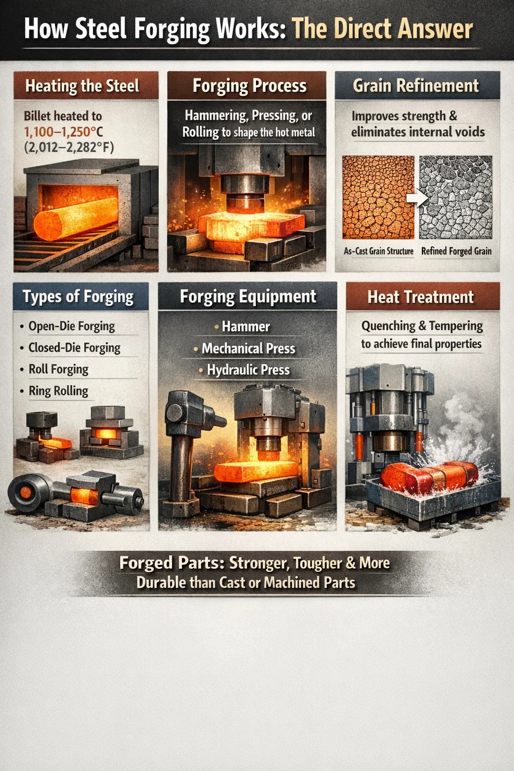
How Steel Forging Works: The Direct Answer
Steel forging is the process of shaping steel by applying compressive force — either through hammering, pressing, or rolling — while the metal is heated to a temperature that makes it plastic and workable but not molten. The result is a part with superior mechanical properties compared to cast or machined components, because the forging process refines the internal grain structure and eliminates internal voids.
In practical terms, a steel billet or ingot is heated to between 1,100°C and 1,250°C (2,012°F to 2,282°F) for hot forging — the most common industrial method — then placed under a press or hammer that deforms it into the desired shape. The shaped part is then cooled under controlled conditions and finished through machining, heat treatment, or surface processing.
This is not a single technique but a family of related processes. Depending on part geometry, production volume, required tolerances, and material grade, manufacturers choose from open-die forging, closed-die (impression-die) forging, roll forging, ring rolling, or isothermal forging. Each delivers different trade-offs between material utilization, die cost, dimensional accuracy, and achievable complexity.
The Raw Material: Choosing the Right Steel for Forging
Not every steel grade forges the same way. The carbon content, alloying elements, and cleanliness of the melt all affect how the material flows under pressure and what properties the finished part achieves. Forgeable steels are broadly grouped as follows:
- Low-carbon steels (0.05–0.30% C): Highly ductile and easy to forge; used for structural parts, bolts, and shafts that don't require extreme hardness.
- Medium-carbon steels (0.30–0.60% C): The workhorse of the forging industry; grades like AISI 1040 and 4140 are used for crankshafts, connecting rods, gears, and axles.
- High-carbon steels (0.60–1.00% C): Harder and stronger but more sensitive to cracking during forging; used for springs, rails, and cutting tools.
- Alloy steels (4000, 8000 series): Chromium, molybdenum, nickel, and vanadium additions improve hardenability and toughness; common in aerospace and heavy machinery.
- Stainless steels (300 and 400 series): Require higher forging pressures and tighter temperature control; used in chemical, food processing, and medical applications.
The forging stock arrives as round bars, billets cut from rolled bar stock, or ingots for very large parts. Billet weight for automotive components typically ranges from 0.5 kg to 30 kg, while large industrial forgings — such as turbine shafts or pressure vessel flanges — can start from ingots weighing several tonnes.
Heating the Steel: Temperature, Furnaces, and Scale Control
Heating is where the forging process actually begins, and it is far more controlled than the image of a glowing bar pulled from a fire suggests. Getting the temperature wrong — even by 50°C — can mean cracked forgings, excessive die wear, or parts that fail inspection.
Forging Temperature Ranges by Steel Type
| Steel Grade | Start Forging Temp (°C) | Finish Forging Temp (°C) | Typical Application |
|---|---|---|---|
| AISI 1020 (low-C) | 1,260 | 900 | Structural brackets, bolts |
| AISI 4140 (Cr-Mo) | 1,230 | 850 | Crankshafts, gears |
| AISI 4340 (Ni-Cr-Mo) | 1,200 | 870 | Aircraft landing gear |
| 304 Stainless | 1,150 | 900 | Valve bodies, flanges |
| H13 Tool Steel | 1,100 | 900 | Die inserts, tooling |
Industrial forging furnaces are gas-fired rotary hearth furnaces, pusher furnaces, or induction heating systems. Induction heating has become dominant for high-volume production of smaller billets because it heats a 50 mm diameter billet to forging temperature in under 60 seconds, eliminates surface scaling almost entirely, and uses roughly 30–40% less energy than equivalent gas furnace systems.
Scale — the iron oxide layer that forms on the surface during gas furnace heating — is a persistent problem. If scale is pressed into the part surface by die contact, it creates surface defects that require additional machining or cause rejection. High-pressure water descaling jets operating at 150–200 bar are standard on press lines to blast scale off immediately before the billet enters the die.
Open-Die Forging: Flexibility for Large and Custom Parts
Open-die forging — also called free forging or smith forging — uses flat, V-shaped, or simple contoured dies that do not enclose the workpiece. The operator or automated system rotates and repositions the billet between each press stroke, gradually working it into the desired shape. This technique gives the forge shop enormous flexibility: a single set of flat dies can produce any number of different part shapes simply by changing how the workpiece is manipulated.
Open-die forging is the method of choice for parts that are too large for closed dies — turbine rotor shafts, ship propeller shafts, large flanges, pressure vessel shells, and mill rolls. Parts produced this way can weigh from a few kilograms up to several hundred tonnes. The 300 MN press at China's Second Heavy Industry Group is one of the largest in the world, capable of forging titanium and steel components for nuclear power plants and aircraft structures.
The process sequence for a large shaft typically looks like this:
- Ingot is cast and allowed to solidify; the top (riser) and bottom (butt) sections with segregation and voids are cropped off, removing up to 20–25% of the original ingot weight.
- Remaining ingot is reheated and upset (compressed axially) to break down the as-cast grain structure and close internal voids.
- The billet is drawn out (elongated) under the press, rotating incrementally between strokes to work the material uniformly.
- Multiple reheats are required for large pieces to maintain working temperature above the finish forging limit.
- The rough forging is rough-machined to remove surface irregularities and checked ultrasonically for internal defects.
Material utilization in open-die forging is lower than in closed-die work — typically 60–75% of the starting ingot weight ends up in the finished forging. The rest is removed as crop, scale, and machining stock. Despite this, for very large or one-off parts, the low die costs make open-die the only economically viable option.
Closed-Die Forging: Precision and High-Volume Production
Closed-die forging — also called impression-die forging — uses matched upper and lower die halves that contain the exact negative impression of the finished part. When the press closes, the heated steel billet fills the die cavity and takes on the precise shape of the impression. Excess metal is squeezed out into a thin ring called flash, which is later trimmed off.
This is the dominant method for high-volume production of structural and mechanical components: automotive connecting rods, steering knuckles, wheel hubs, aircraft wing spars, and hand tools. Modern closed-die forging achieves dimensional tolerances of ±0.5 mm or tighter on medium-sized components, significantly reducing downstream machining compared to casting.
The Multi-Station Die Sequence
Complex parts are rarely forged to final shape in a single blow. The die block is divided into multiple impression stations arranged in sequence:
- Fuller impression: Redistributes metal longitudinally, reducing cross-section at specific points.
- Edger impression: Gathers metal in specific zones and roughly shapes the cross-sectional profile.
- Blocker impression: Pre-forms the workpiece to a shape that closely resembles the final part but with larger radii and more draft.
- Finisher impression: Brings the part to final geometry, forming fine details and tight radii. Flash is generated here.
For a typical automotive connecting rod in AISI 4140, the entire sequence — from inserting the billet to extracting the flash-trimmed forging — takes under 30 seconds on a modern mechanical press rated at 25,000 to 40,000 kN. A single forging line can produce 600 to 1,200 connecting rods per hour.
Flash and Material Utilization
Flash typically represents 10–20% of the billet weight in conventional closed-die forging. Flashless forging — a variant where the die is fully enclosed and the billet volume is precisely matched to the cavity — can eliminate this waste but requires very accurate billet preparation and higher press forces. It is used for parts like gear blanks and bearing rings where material cost savings justify the added complexity.
Roll Forging and Ring Rolling: Specialized Shaping Methods
Beyond the two main die-forging categories, several specialized steel forging processes are worth understanding because they dominate specific product categories.
Roll Forging
In roll forging, the heated billet passes between two counter-rotating rolls with shaped grooves machined into their surfaces. As the billet passes through, the rolls reduce its cross-section and lengthen it, distributing metal in the precise pattern needed for the next forging operation. Roll forging is widely used as a pre-forming step before closed-die forging of elongated parts like connecting rods and leaf spring blanks. It improves material distribution and reduces the number of closed-die impressions required, cutting die wear and cycle time.
Ring Rolling
Ring rolling produces seamless rings by piercing a hole in a disc-shaped forging blank and then expanding it between a driven main roll and an idler roll while flat axial rolls control the ring height. The result is a seamless ring with a continuously flowing grain structure around its circumference — a significant structural advantage over rings cut from plate or fabricated by welding.
Rolled rings range from small bearing races weighing under 1 kg to massive wind turbine flanges and nuclear reactor vessel flanges with outside diameters exceeding 8 meters and weights above 100 tonnes. The aerospace industry relies heavily on ring-rolled titanium and steel components for jet engine casings, frames, and bulkheads.
Cold and Warm Forging: Working Steel Below Red Heat
Hot forging is not the only option. Cold forging — performed at or near room temperature — and warm forging — typically at 650–900°C for steel — offer different combinations of surface finish, dimensional accuracy, and mechanical performance.
Cold Forging
Cold forging of steel relies on work hardening: as the metal deforms plastically, its dislocation density increases and it becomes progressively stronger. Parts produced by cold forging can achieve surface finishes of Ra 0.4–1.6 µm and dimensional tolerances tighter than ±0.05 mm without any machining. The high-volume production of bolts, nuts, screws, and cold-formed gear blanks are primary applications.
The limitation is the large forces required. Cold forging a low-carbon steel requires flow stresses of 500–800 MPa, compared to 80–150 MPa for the same material at hot forging temperatures. Dies wear rapidly, and the steel must typically be annealed and re-lubricated (often with phosphate-soap systems) between stages for multi-pass forming operations.
Warm Forging
Warm forging sits between hot and cold in terms of both temperature and outcome. At intermediate temperatures, flow stress is reduced compared to cold working — lowering press tonnage requirements — while surface quality and dimensional precision are much better than hot forging because less scale forms and thermal shrinkage is smaller. Warm forging is increasingly used for precision gears and CV joint components in the automotive drivetrain, where the combination of near-net-shape accuracy and good surface integrity reduces total manufacturing cost compared to hot-forge-then-machine sequences.
Forging Equipment: Hammers, Mechanical Presses, and Hydraulic Presses
The machine delivering the forging force shapes the economics, capability, and output rate of the operation as much as the die design does. Three main machine types dominate industrial steel forging:
Forging Hammers
Hammers deliver energy by dropping or driving a ram downward at high velocity. The deformation energy is the kinetic energy of the moving ram. Gravity drop hammers are the simplest type; power hammers use steam, compressed air, or hydraulic pressure to accelerate the ram, reaching impact energies from 5 kJ to over 1,000 kJ for large double-acting steam hammers. Hammers are well suited to open-die forging of complex shapes because multiple rapid blows can work the material progressively. The high strain rate of hammer blows also means less die contact time and lower die thermal load.
Mechanical Forging Presses
Mechanical presses use a flywheel-driven eccentric crank to convert rotational energy into a single ram stroke per revolution. Capacities range from 5,000 kN to 125,000 kN. Their fixed stroke and predictable ram position make them ideal for multi-impression closed-die work with tight dimensional repeatability. A 63,000 kN mechanical press — a common size for heavy automotive forgings — typically runs at 40–80 strokes per minute, enabling very high production rates.
Hydraulic Forging Presses
Hydraulic presses generate force through high-pressure fluid acting on a cylinder. Unlike mechanical presses, they can hold full tonnage throughout the stroke and can be programmed with complex ram velocity and force profiles. This makes them essential for isothermal forging of aerospace superalloys, where slow strain rates are needed to avoid adiabatic heating and cracking, and for very large open-die operations. The world's largest forging presses — including the 750 MN press at VSMPO-AVISMA in Russia — are hydraulic.
What Happens to the Grain Structure During Steel Forging
The mechanical superiority of forgings over castings comes directly from what forging does to the steel's internal microstructure. Understanding this explains why forgings are specified for critical applications even when they cost significantly more.
As-cast steel contains a coarse, dendritic grain structure with chemical segregation between grain boundaries and internal shrinkage voids or porosity. When this material is forged, several things happen simultaneously:
- Grain refinement: Large cast grains are broken up by plastic deformation and then recrystallize into smaller, more uniform equiaxed grains during and after hot working. Smaller grains mean better toughness and fatigue strength.
- Void closure: Internal porosity and micro-shrinkage are compacted and welded shut by the compressive stresses of forging, particularly in multi-pass open-die operations with high reduction ratios.
- Fiber flow: Non-metallic inclusions and carbide stringers are elongated and aligned with the direction of metal flow, creating a grain flow pattern. When the forging die is designed correctly, this fiber flow follows the contour of the part, and the grain flow lines run parallel to the stress axis in service — significantly improving fatigue resistance compared to a machined blank where the flow lines are cut through.
- Homogenization: Repeated heating and deformation distributes alloying elements more uniformly, reducing the compositional gradients that weaken cast structures.
A well-forged steel component can exhibit up to 40% higher fatigue strength, 20% higher tensile strength, and markedly superior impact toughness compared to a cast component of the same nominal composition. In applications like aircraft landing gear or automotive crankshafts — where cyclic loading and occasional shock loads are design drivers — these are not marginal gains.
Heat Treatment After Forging: Completing the Metallurgical Cycle
For most alloy steel forgings, the forging operation alone does not deliver the final mechanical properties required. Post-forging heat treatment is the step that locks in the target combination of strength, hardness, and toughness.
Normalizing
Heating to 850–950°C and air cooling refines the grain structure and homogenizes the microstructure after forging. Normalizing is often specified as a baseline treatment for carbon and low-alloy steel forgings before final machining and is sometimes the only heat treatment required for lower-performance applications.
Quench and Temper (Q&T)
For high-performance alloy steel forgings, austenitizing (typically 830–900°C), quenching in water, oil, or polymer, and then tempering at 450–680°C is the standard route to achieve high strength with adequate toughness. An AISI 4340 steel forging in Q&T condition can achieve tensile strengths of 1,000–1,800 MPa depending on the tempering temperature, making it suitable for aircraft structural components and heavy-duty drivetrain parts.
Annealing and Stress Relief
Large forgings with complex geometry can retain significant residual stresses from uneven cooling after forging. A stress-relief anneal at 550–650°C — below the transformation temperature — reduces residual stress without substantially changing hardness, preventing distortion during final machining. This step is standard practice for large valve bodies, die blocks, and pressure vessel components.
Quality Control and Testing in Steel Forging
Steel forgings destined for critical applications undergo a rigorous inspection regime that covers both surface and internal quality. The specific tests required depend on the industry standard — ASTM, EN, JIS, or customer-specific specifications — but the following are broadly applied:
- Ultrasonic Testing (UT): High-frequency sound waves detect internal flaws — cracks, voids, inclusions — that are invisible on the surface. Required for virtually all aerospace, nuclear, and pressure equipment forgings; acceptance criteria are defined by zone (e.g., no indication exceeding 2 mm flat-bottom hole equivalent in the bore zone).
- Magnetic Particle Inspection (MPI): Detects surface and near-surface cracks in ferromagnetic steels by magnetizing the part and applying ferrous particle suspension. Standard for automotive safety-critical forgings like steering knuckles and wheel hubs.
- Hardness Testing: Brinell or Rockwell hardness measured on machined surfaces confirms that heat treatment achieved the target property range.
- Tensile and Impact Testing: Destructive tests on separately forged test coupons — or from prolongations forged onto the part — verify yield strength, ultimate tensile strength, elongation, and Charpy V-notch impact energy at specified temperatures.
- Dimensional Inspection: CMM (coordinate measuring machine) verification of all critical dimensions against the engineering drawing, with full traceability of measurement data.
Macro-etch testing — cutting, polishing, and etching a cross-section of a forging with a dilute acid solution — reveals the grain flow lines, confirms that they follow the intended pattern, and exposes any internal segregation, piping, or seams that UT might miss. This test is commonly specified for first-article qualification of new die designs.
Common Defects in Steel Forgings and Their Causes
Even well-controlled forging operations produce defective parts. Recognizing the root cause of each defect type is essential for correcting the process before large quantities of scrap accumulate.
| Defect | Description | Primary Cause |
|---|---|---|
| Laps and folds | Surface irregularities folded back into part | Incorrect die design or excessive flash that folds back |
| Cold shuts | Oxidized surface skin trapped inside forging | Two metal streams meeting at low temperature |
| Cracking | Surface or internal fracture | Forging below minimum temperature, excessive reduction rate |
| Underfill | Incomplete cavity fill, missing material | Insufficient billet weight or press tonnage |
| Scale pits | Oxide scale pressed into surface | Inadequate descaling before die contact |
| Decarburization | Carbon-depleted surface layer, low hardness | Excessive furnace atmosphere oxidation |
Where Forged Steel Parts Are Used: Industry Applications
Steel forgings are found in virtually every industry where components must withstand high stresses, repeated loading, or elevated temperatures. The following sectors account for the large majority of global forging output:
Automotive Industry
The automotive sector consumes roughly 60% of all forgings produced globally. A typical passenger car contains over 250 forged components: crankshafts, connecting rods, camshafts, transmission gears, steering knuckles, wheel hubs, brake calipers, suspension arms, and CV joint housings. The shift to electric vehicles is changing the mix — fewer crankshafts and pistons — but increasing demand for large battery enclosure structural members and electric motor shafts.
Aerospace and Defense
Aerospace forgings are subject to the most rigorous material and process certification requirements of any industry. Structural airframe components — wing spars, fuselage frames, landing gear struts — and engine components — compressor discs, turbine discs, shafts — are almost exclusively forged. A single wide-body commercial aircraft contains over 1,500 forged parts, many of them large aluminum or titanium pieces rather than steel, but high-strength steel forgings dominate in landing gear and actuation systems.
Oil, Gas, and Power Generation
Pressure vessel flanges, valve bodies, pipeline fittings, wellhead components, and turbine rotors are critical forging applications in the energy sector. These parts operate under high pressure, high temperature, and often corrosive environments where casting porosity would be an unacceptable risk. Large turbine rotor forgings for steam power plants can weigh over 200 tonnes after final machining and require months of forging, heat treatment, and testing before delivery.
Construction and Mining Equipment
Track links, sprockets, bucket teeth, rock drill bits, and structural pins in heavy construction and mining equipment rely on forged steel for its resistance to impact and abrasion. The extremely high dynamic loads seen by these components — a large excavator bucket tooth may absorb tens of thousands of impact cycles per shift — make the superior toughness of forgings essential for acceptable service life.
Modern Developments in Steel Forging Technology
The core physics of steel forging have not changed — metal still flows under pressure when heated — but the technology surrounding the process has advanced substantially over the past two decades.
Finite Element Analysis (FEA) simulation of the forging process — using software such as Deform, FORGE, or Simufact — allows engineers to predict metal flow, strain distribution, die stress, and potential defect locations before cutting a single die. This has dramatically reduced the number of die tryout iterations required for complex new parts, cutting die development time and cost by 30–50% in many cases.
Servo-controlled hydraulic and servo-mechanical presses allow programmable ram velocity profiles, enabling warm and isothermal forging of materials that previously required dedicated equipment or were not feasible at all in die forging. The ram can be slowed at critical stages to control heat generation and metal flow, or accelerated to optimize cycle time on less sensitive operations.
Automated forging cells combining induction heaters, robotic billet handling, multi-axis press transfer systems, and in-line vision inspection have made it possible to run high-volume closed-die forging lines with minimal direct labor. A modern automotive forging line may have one operator supervising four to six presses, with quality inspection handled by laser scanning and machine vision systems at the end of the line.
Precision near-net-shape forging — producing parts so close to final geometry that machining is reduced to a light finishing pass on functional surfaces only — is increasingly common for automotive gears and bearing components. This approach reduces machining time, improves material utilization, and preserves the beneficial grain flow that machining would otherwise destroy at the part surface.