英语
英语 德语
德语 阿拉伯语
阿拉伯语Content
- 1 What Steel Forging Actually Is — and How It Works
- 2 Choosing the Right Steel Grade Before You Forge
- 3 Heating the Steel: Furnace Types, Temperature Control, and Soaking Time
- 4 The Main Steel Forging Methods Compared
- 5 Die Design for Steel Forging: Flash, Draft, and Fillets
- 6 Forging Equipment: Hammers vs. Presses vs. Upsetters
- 7 Post-Forge Heat Treatment: Normalizing, Quenching, and Tempering
- 8 Common Steel Forging Defects and How They Happen
- 9 Inspection and Quality Standards for Forged Steel Parts
- 10 How Forged Steel Compares to Cast and Machined Steel
- 11 Key Industries That Depend on Steel Forging
- 12 Practical Considerations When Sourcing Steel Forgings
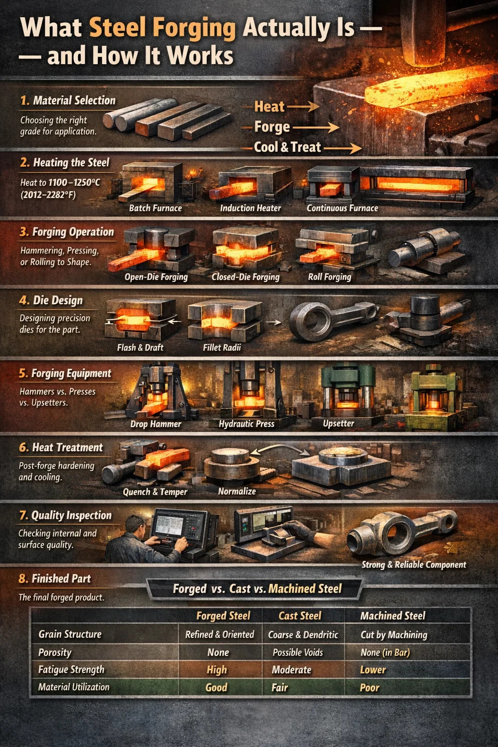
What Steel Forging Actually Is — and How It Works
Steel forging is the process of shaping steel by applying compressive force — either through hammering, pressing, or rolling — while the metal is heated to a temperature between 1,100°C and 1,250°C (2,012°F to 2,282°F). At that range, steel becomes plastic enough to deform without cracking, yet it retains the grain structure that gives forged parts their superior mechanical strength. The result is a component that is structurally denser, tougher, and more fatigue-resistant than anything cast or machined from bar stock.
The short answer to how you forge steel: heat the workpiece to the correct forging temperature, place it under a hammer or press, apply controlled force to shape it to the desired geometry, and then follow a prescribed cooling or heat-treatment cycle to lock in the mechanical properties. Every variable — temperature, force, die geometry, deformation rate, and cooling speed — determines the final quality of the part.
This article walks through the full steel forging process in the order a metallurgist or production engineer would approach it: material selection, heating, the forging operation itself, die design considerations, post-forge treatment, quality inspection, and the practical differences between forging methods. Whether you are sourcing forged components or setting up a forging line, every section here is focused on actionable, specific knowledge rather than generalities.
Choosing the Right Steel Grade Before You Forge
Not every steel grade responds the same way to forging. Carbon content, alloy additions, and cleanliness of the melt all affect how a steel behaves under the hammer and what properties can realistically be achieved afterward. Selecting the wrong grade wastes energy, shortens die life, and produces parts that fail in service.
Low-Carbon Steels (0.05%–0.30% C)
These are the easiest grades to forge. They have a wide forging temperature window, low flow stress, and minimal risk of cracking. Grades like AISI 1018 and 1020 are common for structural brackets, shafts, and agricultural components where toughness matters more than hardness. The limitation is that they cannot be hardened to high levels through heat treatment — tensile strengths typically top out around 550 MPa in the normalized condition.
Medium-Carbon Steels (0.30%–0.60% C)
The workhorses of the steel forging industry. Grades such as AISI 1040, 1045, and 4140 (a chromium-molybdenum alloy) cover the majority of automotive, oil and gas, and heavy machinery applications. After quench and temper, 4140 routinely delivers tensile strengths of 900–1,100 MPa with good ductility. The forging window is narrower than low-carbon grades — typically 1,100°C–1,230°C — and the risk of quench cracking rises, so section size and cooling rate need careful management.
High-Carbon and Tool Steels (0.60%–1.50% C)
Grades like AISI 1080, 52100 (bearing steel), and H13 tool steel are forged at lower temperatures — often below 1,100°C — and require slow, controlled post-forge cooling to prevent thermal cracking. Carbide networks must be broken up and redistributed during forging to achieve uniform hardness in finished tooling or bearings. These grades demand experienced operators and close pyrometer control.
Stainless and Heat-Resistant Steels
Austenitic stainless grades (304, 316) have high work-hardening rates, which means forging loads are significantly higher than for plain carbon steel. Martensitic grades (410, 420) forge more easily but require careful annealing between forging passes. Precipitation-hardening grades like 17-4 PH are forged at 1,065°C–1,175°C and then aged to develop their final properties — a two-stage thermal cycle that must be respected precisely.
| Steel Grade | Carbon Content | Forging Temp Range | Typical Application | Max Tensile (Q&T) |
|---|---|---|---|---|
| AISI 1020 | 0.18–0.23% | 1,150–1,280°C | Structural brackets, shafts | ~550 MPa |
| AISI 4140 | 0.38–0.43% | 1,100–1,230°C | Crankshafts, flanges, gears | 1,000–1,100 MPa |
| AISI 52100 | 0.98–1.10% | 1,040–1,120°C | Bearing rings, races | 2,000 MPa (hardened) |
| AISI H13 | 0.32–0.45% | 1,065–1,175°C | Hot-work tooling, dies | 1,200–1,650 MPa |
| AISI 316 SS | ≤0.08% | 1,100–1,260°C | Valves, fittings, marine parts | ~620 MPa (annealed) |
Heating the Steel: Furnace Types, Temperature Control, and Soaking Time
Heating is where most forging defects originate. Overheating causes grain coarsening and incipient melting at grain boundaries — a condition called "burning" that is irreversible. Underheating leaves the core cold, increases flow stress, and promotes cracking during deformation. Getting the furnace right is not optional.
Furnace Types Used in Steel Forging
- Batch (box) furnaces — suited to low-volume production and large billets. The steel is charged, the door closed, and the entire load heats to temperature. Good temperature uniformity but slow throughput.
- Continuous (rotary hearth or pusher) furnaces — billets move through zones of increasing temperature. Common in high-volume forging lines producing automotive connecting rods, axle beams, and similar parts at rates exceeding 500 pieces per hour.
- Induction heaters — electromagnetic coils heat the billet in seconds rather than minutes. Temperature uniformity is excellent for round billets, energy efficiency is high (up to 90% versus 40–50% for gas furnaces), and scale formation is minimal. Widely used in precision closed-die forging.
- Salt bath furnaces — used for small, complex tool steel components that need uniform heating without oxidation. Less common in bulk forging but critical for high-value precision parts.
Soaking Time and Through-Heating
A billet that shows the right surface color may still have a cold core. The general rule of thumb in industrial forging practice is 1 hour of soak time per 25 mm of cross-section for carbon and alloy steels in a gas-fired furnace. For a 200 mm diameter billet, that means at least 8 hours at temperature before it is safe to forge. Induction heating eliminates most of this waiting time but requires precise power and frequency matching to the billet diameter.
Scale formation during heating is unavoidable in open-atmosphere furnaces. A thin oxide layer — typically 0.5–2 mm — forms on the surface and must be removed by descaling (shot blast, water jets, or die impression) before or during the first forging strike. Scale trapped under the die surface causes pitting defects and die damage.
Temperature Measurement
Experienced smiths historically judged temperature by color — bright yellow-white corresponds roughly to 1,200°C–1,300°C, and orange-yellow to 1,000°C–1,100°C. In modern production forging, optical pyrometers and infrared sensors provide continuous, non-contact temperature readings with accuracy to ±5°C. Thermocouples embedded in furnace walls track ambient temperature, while optical pyrometers measure the billet surface as it exits the furnace. For critical aerospace or defense forgings, thermocouple surveys are logged and retained as part of the quality record.
The Main Steel Forging Methods Compared
Steel forging is not a single process — it encompasses several distinct methods, each suited to different part geometries, production volumes, and tolerance requirements. Understanding the differences is essential when selecting a supplier or designing a component for forgeability.
Open-Die Forging (Cogging, Drawing Out, Upsetting)
In open-die forging, the steel is worked between flat or simply shaped dies that do not enclose the workpiece. The operator repositions and rotates the billet between hammer blows to shape it progressively. This method is used for large, simple shapes — shafts, discs, rings, and blocks — and for ingot breakdown to refine the coarse as-cast grain structure.
Parts weighing anywhere from a few kilograms to over 300 tonnes are produced this way. The Forging Industry Association estimates that open-die forgings can reach diameters of 3 meters or more for heavy industrial applications such as hydroelectric turbine shafts and nuclear reactor pressure vessel heads. Dimensional tolerances are loose compared to closed-die work — typically ±3–10 mm — so significant machining allowance is built in.
Closed-Die (Impression-Die) Forging
This is the dominant steel forging method for precision components. Upper and lower dies contain mirror-image impressions of the desired part shape. When the heated billet is struck or pressed, material flows to fill the cavity and excess metal squeezes out as flash around the parting line. The flash is trimmed in a separate operation.
Closed-die forging achieves tolerances of ±0.5–1.5 mm on critical dimensions and can produce near-net-shape parts that require minimal finish machining. Automotive connecting rods, crankshafts, wheel hubs, and suspension components are almost universally made by this method. A typical automotive connecting rod forging line running at 300 pieces per hour is a standard benchmark for high-volume production.
The process typically involves multiple die stations: edging (or fullering) to redistribute material, blocking (rough shape), finishing (final geometry), and trimming. Each station adds cost to the tooling but reduces the work required at each subsequent stage and improves material utilization.
Roll Forging and Cross-Wedge Rolling
Roll forging passes a heated billet between shaped rolls to elongate and redistribute material along the length. It is often used as a preforming step before closed-die forging — for example, shaping the long tapered preform for a connecting rod before final impression. Cross-wedge rolling (CWR) uses two rotating dies with wedge-shaped projections to form axisymmetric parts like ball joint pins, axle journals, and valve stems at very high speeds — up to 600 pieces per minute on optimized lines.
Isothermal and Hot-Die Forging
In conventional forging, dies are significantly cooler than the workpiece (typically 200–300°C versus 1,100–1,200°C for the steel). This temperature differential chills the surface of the billet on contact, increasing flow stress and limiting how complex a shape can be achieved in one press stroke. Isothermal forging heats the dies to near-workpiece temperature, reducing chilling and allowing very precise, near-net-shape production of complex aerospace components. It is expensive and slow — primarily reserved for titanium alloys and nickel superalloys — but the principle is occasionally applied to specialty steel forgings for aerospace structural parts where material buy-to-fly ratios must be minimized.
Cold Forging of Steel
Cold forging shapes steel at room temperature or slightly elevated temperatures (below the recrystallization threshold of approximately 450°C for carbon steels). The absence of heating means no scale, excellent surface finish, and tight tolerances — fasteners, ball studs, and precision pins are typically cold-forged. The tradeoff is high flow stress and significant work hardening; press loads are 3–5 times higher than for hot forging of the same material, and intermediate annealing between forming stages is often required to restore ductility.
Die Design for Steel Forging: Flash, Draft, and Fillets
Die design is one of the most technically demanding aspects of the forging process. A poorly designed die produces defects, consumes excessive material, and wears out quickly. The following parameters are the foundation of any closed-die forging tool design.
Flash Land and Flash Gap
Flash is the thin fin of steel that escapes between the die halves at the parting line. Rather than being pure waste, the flash land creates back-pressure that forces material into thin ribs and complex cavities. The flash gap (thickness of the land) is typically 1–3% of the part's projected height. Too wide a gap wastes material; too narrow a gap raises die loads to dangerous levels. Flash weight on a typical automotive forging accounts for 15–20% of the billet weight, which is trimmed off and recycled.
Draft Angles
All vertical walls in a forging must be tapered — inclined at an angle relative to the direction of die travel — so the part releases from the die without tearing. Standard draft angles for steel forging are 5–7° on external surfaces and 7–10° on internal surfaces. Steep-draft areas lock the part against ejection; insufficient draft causes die galling and surface tearing. Die design software such as Deform, Simufact, or QForm now allows engineers to simulate metal flow and predict underfill, laps, and die wear before cutting a single piece of tool steel.
Fillet and Corner Radii
Sharp internal corners in a die cavity create stress concentration in the die material and produce folds (laps) in the forging. A minimum fillet radius of 3–6 mm is standard for steel forgings; in high-stress areas such as web-rib junctions on flanges, radii of 8–12 mm are common. Designers sometimes push for tight radii to reduce machining stock, but undersize fillets consistently cause premature die failure — die life drops from 10,000+ pieces to under 3,000 pieces when corner radii are halved below the recommended minimum.
Parting Line Location
The parting line — where the two die halves meet — must be located to allow the part to be removed, minimize die mismatch risk, and place flash in a position where trimming is straightforward. For symmetrical parts, a straight parting line through the largest cross-section is standard. Asymmetric parts or those with undercuts may require a stepped or compound parting line, which adds die complexity and cost.
Forging Equipment: Hammers vs. Presses vs. Upsetters
The choice of forging equipment shapes what geometries are achievable, how fast production runs, and what capital investment is required. The three primary categories — hammers, presses, and upsetters — each have distinct operating characteristics.
Drop Hammers (Gravity and Power-Assisted)
A hammer forges steel by impact — the ram falls and decelerates rapidly against the workpiece, delivering energy as an impulsive blow. Gravity hammers are rated by ram weight (e.g., 1 tonne to 25 tonnes); power-assisted hammers (steam, pneumatic, or hydraulic counterblow) extend the energy range substantially. The impact rate and velocity are high, which promotes dynamic recrystallization in steels and produces fine-grained forgings. Hammers excel at complex shapes with deep ribs but generate significant vibration and noise. Their stroking rates of 60–120 blows per minute allow rapid multi-blow sequences on a single heat.
Mechanical and Hydraulic Forging Presses
Presses apply force at a controlled, slower rate — squeeze rather than impact. Mechanical crank presses range from 500 tonnes to 12,000 tonnes and operate at fixed stroke positions, making them highly repeatable and suited to automated transfer lines. Hydraulic presses can reach 50,000 tonnes or more for large aerospace structural forgings and allow the ram speed and stroke to be varied — useful for forging temperature-sensitive alloys or for multi-step forming in a single die set.
Press forgings typically show better dimensional consistency than hammer forgings because the ram position at bottom dead center is fixed. The slower deformation rate also allows heat to dissipate from the surface, which can be either an advantage (finer surface grain) or a disadvantage (reduced hot ductility in the skin) depending on the alloy.
Upset Forging Machines (Upsetters)
An upsetter grips a bar end and applies horizontal force to compress and expand it — the process of upsetting increases the cross-section while reducing the length. This is how bolt heads, flanged fittings, and valve stems are formed. Upsetters apply 400–4,000 tonnes of clamping and forging force in the horizontal plane and operate at high production rates with minimal operator intervention. Material utilization is excellent because little or no flash is generated.
Post-Forge Heat Treatment: Normalizing, Quenching, and Tempering
The properties of a steel forging are only partially determined by the forging operation itself. Post-forge heat treatment controls the final microstructure and mechanical properties, often making the difference between a part that meets specification and one that fails in service.
Normalizing
Normalizing heats the forging to 50–60°C above the upper critical temperature (Ac3) — typically 870–950°C for medium-carbon steels — and then cools it in still air. This refines and homogenizes the grain structure disrupted by uneven deformation, relieves internal stresses, and produces a consistent baseline microstructure for subsequent machining or heat treatment. Normalized 1045 steel typically achieves a tensile strength of 580–640 MPa — adequate for many structural applications without further treatment.
Annealing
Full annealing involves austenitizing (heating above Ac3) followed by very slow furnace cooling — often at controlled rates of 10–25°C per hour. The result is the softest, most machinable condition of the steel. High-carbon and tool steel forgings are typically annealed before finish machining, then re-hardened and tempered to final hardness. Process (sub-critical) annealing, conducted just below Ac1, softens cold-worked forgings without full transformation.
Quench and Temper (Q&T)
This is the most demanding and most commonly specified heat treatment for high-strength forged steel components. The forging is austenitized (typically 840–870°C for 4140), then rapidly quenched in oil, water, or polymer solution to transform the austenite to martensite — a hard, brittle phase. The quenched part is then tempered by reheating to 200–650°C; the higher the tempering temperature, the more ductility is restored at the cost of hardness and tensile strength.
A 4140 forging quenched in oil and tempered at 315°C achieves approximately 1,550 MPa tensile / 1,380 MPa yield / 11% elongation. Tempered at 595°C, the same material produces approximately 980 MPa tensile / 830 MPa yield / 20% elongation. The trade-off between strength and ductility must be matched to the application's fatigue, impact, and static load requirements.
Controlled Cooling (Forged-and-Cooled Microalloyed Steels)
Microalloyed steels containing vanadium, niobium, or titanium (V-Nb-Ti grades) can achieve mechanical properties comparable to Q&T steels by controlling the cooling rate directly after forging — eliminating the separate quench-and-temper furnace cycle. This "direct cooling" or "controlled thermomechanical processing" reduces energy consumption and cycle time by 30–40% compared to conventional Q&T, and is now standard for automotive connecting rods and steering knuckles in high-volume production.
Common Steel Forging Defects and How They Happen
Forging defects fall into two broad categories: those that originate in the incoming material and those generated during the forging process itself. Knowing the root cause of each defect type is the only reliable way to prevent recurrence.
Laps and Cold Shuts
A lap forms when folded metal is pressed against the die surface without welding — the surfaces touch but do not bond because they have oxidized. On inspection, a lap appears as a tight linear crack, often at 45° to the surface. Cold shuts are similar but arise from two metal streams meeting at insufficient temperature to fuse. Both defects render a forging non-conforming and typically scrap it unless they are so shallow they can be removed within machining allowance. Root causes: incorrect preform shape, insufficient forging temperature, excessive flash restriction preventing material flow.
Underfill and Die Missrun
Underfill occurs when the die cavity is not completely filled — typically in thin ribs, deep pockets, or sharp corners. It is caused by insufficient billet volume, a billet positioned off-center, insufficient forging energy, or a cold billet that has lost temperature before the final stroke. Underfill in critical cross-sections reduces the load-carrying area and must be rejected.
Internal Voids and Pipe
Shrinkage porosity and pipe (the central cavity in an as-cast ingot) must be eliminated during the breakdown forging stages. If the forging reduction ratio is insufficient — typically a minimum of 4:1 reduction in area is specified for aerospace-grade forgings — remnant porosity or pipe can persist into the finished part. Ultrasonic testing (UT) at 5 MHz is the standard method for detecting internal voids in finished forgings.
Grain Flow Anomalies
The directional grain flow (fiber structure) developed during forging is one of the primary advantages over cast or machined parts. If the forging process is poorly designed, the grain flow can be cut by machining, disrupted by improper material flow, or oriented perpendicular to the primary load direction. This significantly reduces fatigue life — fatigue strength transverse to the fiber direction can be 30–50% lower than in the longitudinal direction. Macroetch tests on cross-sectioned forgings reveal the grain flow pattern and are often required on first-article inspection pieces.
Overheating and Burning
Overheating (above the recommended forging temperature but below melting) causes exaggerated grain growth that reduces toughness and fatigue properties. The part may be salvageable with a normalizing treatment if no burning has occurred. Burning — partial melting of grain boundary films of low-melting-point phases (sulfides, phosphides) — is irreversible. A burned forging must be scrapped regardless of its dimensional appearance. This is why pyrometer control and furnace calibration are mandatory in certified forging operations.
Inspection and Quality Standards for Forged Steel Parts
Steel forgings intended for critical applications are subject to a comprehensive inspection regime covering dimensional, surface, and internal quality. The applicable standards vary by industry but share common methods.
- Dimensional inspection: CMM (coordinate measuring machine) or manual gauging against the forging drawing. First-article inspection (FAI) typically measures 100% of critical dimensions; production inspection samples according to an AQL plan (e.g., AQL 1.0 for critical features).
- Magnetic particle inspection (MPI): Detects surface and near-surface cracks in ferromagnetic steels. Standard for automotive, oil and gas, and aerospace forgings per ASTM E1444 / EN ISO 9934.
- Liquid penetrant testing (LPT): Used for non-magnetic steels (austenitic stainless) or where MPI is impractical. Detects surface-breaking defects only.
- Ultrasonic testing (UT): Detects internal voids, inclusions, and cracks at depth. Aerospace forgings are typically required to meet AMS 2630 (Class A or B) ultrasonic cleanliness requirements.
- Mechanical testing: Tensile, hardness, Charpy impact, and fatigue specimens are cut from integral test prolongations or separately forged test pieces. Results must meet minimum values per the applicable material specification (e.g., AMS 6349 for 4340 steel forgings).
- Macroetch and microstructure examination: Cross-sections are etched to reveal grain flow and checked metallographically for grain size (per ASTM E112), decarburization depth, and the absence of laps, seams, or inclusions.
For aerospace applications, forgings must additionally be traceable to a specific ingot heat through lot documentation — the entire chain from raw steel melt to finished part is documented and retained for the life of the airframe, often 30+ years.
How Forged Steel Compares to Cast and Machined Steel
A question that arises in almost every design review: why pay the tooling cost and process complexity of forging when casting or machining from bar stock can produce the same external shape? The answer lies in the internal microstructure and the performance under cyclic and impact loading.
| Property | Forged Steel | Cast Steel | Machined from Bar |
|---|---|---|---|
| Grain structure | Refined, directional fiber flow | Coarse, random dendrites | Rolled bar grain — cut by machining |
| Porosity | Essentially none | Possible shrinkage voids | None (in wrought bar) |
| Fatigue strength | High (100%) | 60–80% of forged | 70–90% of forged (grain cut) |
| Impact toughness | Excellent | Lower (cast segregation) | Good (depends on orientation) |
| Tooling cost | High ($5,000–$200,000+) | Moderate ($2,000–$50,000) | Low (no tooling) |
| Material utilization | Good (near-net-shape) | Good (near-net-shape) | Poor (significant chip waste) |
| Best suited for | High-stress, high-cycle parts | Complex geometry, low-medium stress | Low volume, complex shape |
The fatigue advantage of forged steel is the most commercially important differentiator. In applications such as automotive connecting rods, where 10⁸ load cycles over the component life are routine, the directed grain flow of a forging is not a theoretical benefit — it is a measured, documented performance margin that casting cannot match at equivalent weight and section size.
Key Industries That Depend on Steel Forging
Steel forging is not confined to a single sector. The combination of high strength, reliable internal soundness, and design flexibility makes forged steel components the default choice wherever component failure would have serious safety or economic consequences.
- Automotive: Crankshafts, connecting rods, camshafts, steering knuckles, control arms, CV joint housings, wheel hubs. The global automotive steel forging market was valued at over $20 billion in recent years, with a single mid-size passenger vehicle containing 40–60 kg of forged steel components.
- Oil and gas: Flanges, valves, tees, wellhead components, drill collars, and Christmas tree fittings. Forgings for sour service (H₂S environments) must meet NACE MR0175 / ISO 15156 hardness limits to prevent sulfide stress cracking.
- Aerospace: Wing attachment fittings, landing gear components, bulkheads, and engine mounts. The buy-to-fly ratio of aerospace forgings — the weight of raw billet divided by the finished part weight — has driven investment in near-net-shape forging to reduce titanium and nickel alloy waste, but steel forgings remain critical for structural airframe elements.
- Power generation: Turbine rotors, generator shafts, pressure vessel heads, and boiler fittings. Open-die forged rotors for large turbines can weigh 200+ tonnes and take months of progressive forging and heat treatment to complete.
- Construction and mining equipment: Gear blanks, sprockets, axle housings, bucket pins, and track links. Wear resistance and impact toughness take priority over dimensional precision in these applications.
- Defense: Gun barrels, projectile bodies, armor plate connections, and vehicle drive train components. Mil-spec forgings require certified material traceability and witness testing by government inspectors.
Practical Considerations When Sourcing Steel Forgings
If you are a buyer or design engineer sourcing forged steel parts rather than operating a forge yourself, the following factors determine whether a supplier can reliably deliver to your requirements.
Press Capacity and Forge Weight Capability
Every forging shop has a maximum press tonnage or hammer energy that sets an upper limit on what part sizes and material flow stresses it can handle. Confirm the supplier's largest press size against the projected forging load for your part — simulation software (Deform, QForm) can estimate required tonnage within ±15% accuracy. A forge house operating below 60% of its rated capacity on your job has better die protection and more energy reserve than one running at the limit.
Heat Treatment and Testing Capability In-House vs. Outsourced
Many smaller forges outsource heat treatment and non-destructive testing. This is not automatically a problem, but it adds lead time and another quality chain link. For critical applications, verify that the heat treatment subcontractor is NADCAP-accredited (in aerospace) or holds equivalent qualification, and that NDE is performed by certified Level II or Level III technicians per ASNT SNT-TC-1A or EN ISO 9712.
Lead Time Realities
New die design and manufacture typically takes 6–16 weeks depending on die complexity, the forge shop's die room capacity, and whether simulation-based tryout is used. First-article production and inspection adds another 4–8 weeks for certified forgings. Budgeting less than 20 weeks total from drawing release to first conforming parts is optimistic for a new closed-die steel forging program. Re-orders from existing dies can be delivered in as little as 4–8 weeks depending on furnace scheduling and post-forge treatment queues.
Minimum Order Quantities and Tooling Amortization
Closed-die tooling for a typical automotive-class component costs $20,000–$80,000. At low volumes, this cost dominates unit price. A common breakeven analysis: if the tooling is $40,000 and run quantity is 500 pieces, tooling adds $80 per piece — often acceptable. At 5,000 pieces, it adds $8 per piece. At 50,000 pieces annually (as in automotive series production), tooling cost is essentially irrelevant against per-piece processing cost. Discuss tooling ownership and life guarantee (typically 50,000–200,000 pieces for H13 dies in steel forging) before committing to a long-term supply agreement.